
Destructive testing measures weld strength in laminated tubes by applying force until failure occurs. Mechanical and interlaminar shear strength tests reveal how well the weld holds under stress. Proper sample preparation ensures accurate results, while welding parameters influence the final strength. The table below compares destructive and non-destructive methods:
| Aspect | Destructive Testing (DT) | Non-Destructive Testing (NDT) |
|---|---|---|
| Impact on Material | Damages the material | No damage |
| Results | Precise, quantifiable | Broader sample coverage |
| Cost | More expensive, time-consuming | Cost-effective |
| Sample Size | Limited specimens | Multiple tubes |
| Detection of Defects | May miss minute defects | Detects minute defects |
Key Takeaways
- Destructive testing measures weld strength by applying force until failure, providing precise data on weld integrity.
- Proper sample preparation and consistent layer thickness are crucial for accurate test results and improved weld strength.
- Understanding welding parameters, such as arc length and weld speed, enhances the quality and repeatability of welds.
- Regular analysis of test results helps identify defects and improve manufacturing processes for laminated tubes.
- Implementing best practices in weld testing leads to stronger joints and reduces the risk of failures during service.
Laminated Tubes and Weld Quality
Tube Structure
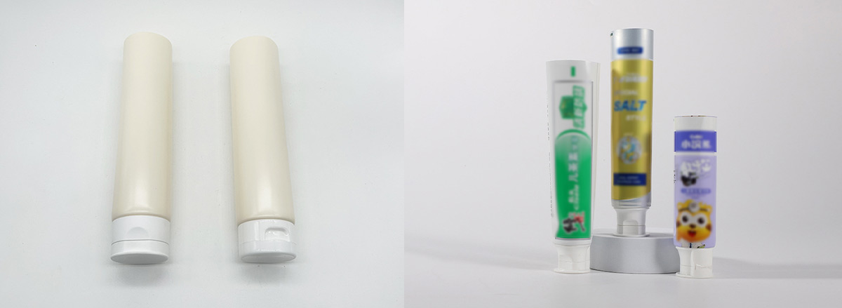
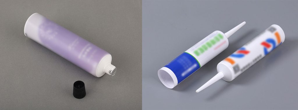
Laminated tubes feature multiple layers, each designed to provide specific properties such as barrier protection, flexibility, and printability. The structure often includes a combination of plastic, aluminum, and adhesive layers. These layers interact at the weld joint, where the integrity of the weld determines the tube’s overall performance.
- Laminations in welded pipes cause non-uniform load distribution in weld joints.
- This non-uniform load can lead to layerwise destruction of defective areas, compromising weld integrity.
- Detecting laminations thinner than 100 μm is difficult, complicating weld strength assessment.
The complexity of laminated tubes makes it essential to understand how each layer responds to welding. Engineers must consider the thickness and material of each lamination when designing tubes for specific applications.
Weld Strength Factors
Several factors influence the strength of welds in laminated tubes. Material selection, layer thickness, and tube geometry play important roles. The presence of thin laminations can make welds more susceptible to failure, especially if defects exist within the layers.
Tip: Consistent layer thickness and high-quality materials improve weld strength and reduce the risk of defects.
Weld strength also depends on the welding process itself. Parameters such as electrode tip diameter, arc length, weld speed, and welding current affect the final result. Arc pulsing, a technique that alternates the weld current rapidly, creates overlapping spot welds and reduces heat input. This method enhances both the quality and repeatability of welds in laminated tubes.
Role of Lami Tube Making Machine
The lami tube making machine plays a critical role in producing high-quality laminated tubes. Operators adjust machine settings to control weld characteristics. The following table highlights how electrode tip size impacts weld performance:
| Smaller Tip | Larger Tip |
|---|---|
| Easy arc starting | Usually harder to start |
| Good arc stability | More chance of arc wander |
| Less weld penetration | More weld penetration |
| Shorter electrode life | Longer electrode life |
Operators also monitor arc length, weld speed, and welding current to ensure consistent welds. Proper calibration of the laminated tube making machine helps maintain weld quality and minimizes defects in laminated tubes.
Destructive Test Methods
Destructive testing provides essential data about the weld strength of laminated tubes. Engineers use several methods to evaluate the integrity of welds, focusing on how the tube performs under stress. Each test method targets specific properties, such as peel strength, burst resistance, tensile performance, and interlaminar shear strength. Proper specimen preparation ensures reliable results, and the lami tube making machine plays a key role in producing consistent samples for testing.
Peel Test
The peel test measures the force required to separate layers at the weld joint of a laminated tube. This test helps determine the adhesive quality and the weld’s resistance to delamination. Technicians follow a systematic procedure:
- Prepare the test samples by bonding two materials using the same process as the lami tube making machine.
- Mount the sample in a universal testing machine (UTM), securing one end in the upper grip and inserting the free end into the lower grip at the required peel angle.
- Set the test parameters, including speed, data acquisition rate, and safety limits.
- Start the test, allowing the UTM to peel the materials apart while measuring the force.
- Collect data on peel force and crosshead displacement.
- Perform analysis to calculate average peel strength and plot graphs of peel force versus displacement.
Note: Peel tests reveal weaknesses in welds caused by uneven thickness or poor adhesion between layers. Consistent sample preparation, such as cutting specimens to 100mm length and slitting them longitudinally, improves the accuracy of results.
Burst Test
The burst test evaluates the maximum pressure a laminated tube can withstand before failure. This test identifies the weakest point in the weld and assesses the overall seal integrity. The procedure involves several steps:
- Insert the tube into the burst tester.
- Screw the tube onto the threaded mandrel.
- Close the door to prepare for testing.
- Press the start button to begin the test cycle.
- The machine inflates the tube and applies the set pressure for a specified time.
Technicians use equipment such as leak burst testers and MSD single-head tube burst testers. These machines inject air into the tube until it bursts, displaying the maximum burst pressure. The burst test can include a hold phase, where the tube is held at a set pressure for five seconds before increasing pressure until failure occurs. This approach allows for detailed analysis of weld strength and tube thickness effects.
Tip: Burst tests provide valuable data for quality control, especially when evaluating tubes produced by different settings of lami tube making machine.
Tensile Test
The tensile test measures the force required to pull a welded laminated tube apart. This test determines the tube’s yield strength, ultimate strength, and elongation. Specimen preparation involves cutting the tube to a standard length, often 100mm, and slitting it longitudinally to expose the weld area. The universal testing machine applies a controlled tensile load until the tube fails.
Engineers use the tensile shear test to assess the weld’s ability to resist forces that try to slide the layers past each other. The following table shows typical tensile strength values for welded laminated tubes used in packaging applications:
| Grade | Yield Strength (ksi) | Ultimate Strength (ksi) | Elongation (%) |
|---|---|---|---|
| 1008 | 30 | 42 | 15 |
| 1020 | 38 | 52 | 12 |
| 340XF | 49 | 64 | 22 |
| 420YF | 61 | 75 | 16 |
| 550YF | 80 | 94 | 12 |
Engineers analyze tensile test results to identify weld defects, variations in thickness, and inconsistencies in lami tube production. The tensile shear test provides insight into the weld’s ability to withstand mechanical stress.
Interlaminar Shear Strength Test
The interlaminar shear strength (ILSS) test evaluates the resistance of a laminated tube’s weld to forces that cause layers to slide over each other. This test is crucial for understanding how well the weld holds under shear stress, especially in tubes with multiple thin layers. Specimen preparation includes cutting the tube to the required length and slitting it to expose the weld area.
Technicians use a universal testing machine to apply a controlled shear load. The tensile shear test measures the force needed to initiate sliding between layers. Analysis of ILSS data helps engineers determine the weld’s effectiveness and identify areas where thickness variations or poor adhesion may lead to failure.
Consistent thickness and proper calibration of the lami tube making machine improve interlaminar shear strength. Regular analysis of ILSS test results supports ongoing quality control and process optimization.
Non-Destructive Testing vs. Destructive Testing
Non-destructive testing and destructive testing serve different purposes in evaluating laminated tube welds. The following table highlights the main differences between these two approaches:
| Aspect | Non-Destructive Testing (NDT) | Destructive Testing (DT) |
|---|---|---|
| Purpose | Detects flaws without damage | Determines material properties through failure |
| Impact on Component | No damage | Component is destroyed |
| Cost Implications | Generally lower long-term costs | Higher costs due to component loss |
| Applications | Safety-critical industries | Research and development |
| Data Provided | Identifies defects | Provides mechanical properties |
Visual and Dimensional Inspection

Visual and dimensional inspection remains a fundamental step in quality control for laminated tubes. Technicians quickly identify surface defects such as cracks, incomplete welds, or misalignments. This method allows for rapid screening of large batches. Visual inspection, combined with dimensional checks, ensures that tubes meet required specifications for diameter, wall thickness, and weld alignment. While this approach cannot reveal hidden flaws, it provides an essential first line of defense against obvious defects.
Visual inspections are crucial as they allow for the quick identification of surface defects, while non-destructive testing methods like Eddy Current Testing and Ultrasonic Testing are essential for detecting internal flaws. This multi-layered approach, combining visual inspections with NDT, ensures comprehensive weld quality assessment, highlighting the effectiveness of visual and dimensional inspections in detecting weld defects in laminated tubes compared to destructive tests.
Ultrasonic Wall Thickness Test
Ultrasonic wall thickness tests use high-frequency sound waves to measure the thickness of tube walls without causing any damage. Technicians place a probe on the tube surface, and the device sends ultrasonic pulses through the material. The equipment calculates wall thickness based on the time it takes for the sound waves to reflect back. This method detects variations in wall thickness and can identify internal defects such as voids or delaminations. Ultrasonic testing provides reliable data for quality assurance and helps maintain consistent tube production.
Chemical Analysis
Chemical analysis verifies the composition of materials used in laminated tubes. Technicians use techniques such as X-ray fluorescence (XRF) or spectroscopy to identify the elements present in each layer. This process ensures that the correct materials have been used and that no contamination has occurred during manufacturing. Chemical analysis supports both non-destructive testing and destructive testing by confirming material integrity and compliance with industry standards.
Test Data and Failure Analysis
Data Collection
Accurate data collection forms the foundation of weld strength evaluation in laminated tubes. Technicians record measurements and observations during destructive testing to ensure comprehensive analysis. They use standardized procedures to maintain consistency and reliability. The following table summarizes key testing methods and their descriptions:
| Testing Method | Description |
|---|---|
| Nick Break Testing | Involves pre-cutting the surface and applying force to analyze internal defects like slag inclusions. |
| Interlaminar Shear Strength (ILSS) | Tests the shear strength of laminates to assess matrix quality and bonding. |
| Impact Testing | Evaluates the material’s resistance to sudden forces, important for understanding durability. |
Technicians document test parameters, sample dimensions, and environmental conditions. They also note the location and type of small-scale defects observed during each test. Consistent data collection helps engineers compare results across batches and identify trends that affect structural safety and overall quality.
Tip: Recording every observation, including minor changes in weld appearance or unexpected test outcomes, improves the accuracy of failure analysis.
Defects Identification
Identifying defects in welded laminated tubes is essential for maintaining product quality and ensuring structural safety. Technicians use destructive testing to reveal both large and small-scale defects that may not be visible during non-destructive inspection. The most common defects found during analysis include:
- Scarf Width
- Scarf Depth
- Scarf Defect
- Deflection
- Mismatch
- Freeze Line
- Undercut
- Left/Right Slope Angle
- Bead Height
- Bead Width
- Bead Roll
- Bead Ratio
The freeze line defect indicates incomplete fusion at the weld joint. This defect can cause significant failures, especially in high-stress applications. The undercut defect appears as an unintentional groove along the weld, often detected through visual examination and confirmed by destructive metallurgical analysis. Small-scale defects such as bead roll or mismatch may seem minor but can compromise the tube’s performance over time.
Technicians pay close attention to scarf defects and bead height, as these often signal problems with the lami tube making machine settings. By cataloging all observed defects, engineers can adjust manufacturing processes to reduce their occurrence and improve overall quality.
Failure Modes
Understanding failure modes in welded laminated tubes helps engineers design safer and more reliable products. Failure modes describe how and why a tube fails under stress. The most common failure modes include delamination, brittle fracture, ductile tearing, and shear failure. Delamination occurs when layers separate due to weak bonding or the presence of small-scale defects. Brittle fracture results from sudden crack propagation, often linked to freeze line or undercut defects.
Shear failure typically arises in tubes with poor interlaminar shear strength. Ductile tearing involves gradual deformation before rupture, which may indicate good weld quality but insufficient material toughness. Technicians analyze the location and nature of each failure to determine its root cause. They use this information to improve weld parameters and minimize the risk of future failures.
Note: Regular analysis of failure modes and defects supports continuous improvement in tube manufacturing and enhances structural safety.
Engineers rely on detailed records of small-scale defects and failure modes to refine welding techniques and optimize settings of lami tube making machine. This approach ensures consistent quality and reduces the likelihood of unexpected failures in service.
Best Practices for Weld Testing
Quality Control Tips
Weld testing for laminated tubes demands strict attention to detail. Technicians who follow best practices improve both the reliability and consistency of welded joints. The following steps help ensure high-quality results:
- Adhere to established welding procedures and specifications for every test.
- Require welders to complete thorough qualification processes before handling resistance spot welding tasks.
- Apply post-weld heat treatment to relieve residual stresses and enhance the properties of welded materials.
- Use corrosion protection methods to extend the lifespan of welded tubes.
- Assign only trained and certified personnel to perform non-destructive testing, such as ultrasonic testing or computed tomography.
- Conduct careful visual inspections to catch surface defects early.
- Utilize ultrasonic testing to find internal flaws that could weaken resistance spot welding joints.
- Employ liquid penetrant testing to reveal surface cracks or porosity.
- Use magnetic particle testing for detecting surface and near-surface defects in ferrous welded materials.
- Keep detailed documentation for every welding test to support traceability and quality assurance.
- Calibrate and validate all non-destructive testing equipment regularly.
- Provide ongoing training for welders and inspectors to maintain high standards.
Tip: Consistent application of these steps leads to stronger welded joints and fewer failures during destructive testing.
Avoiding Common Pitfalls
Many issues in weld testing arise from preventable mistakes. Technicians can avoid these pitfalls by focusing on preparation and process control:
- Clean and prepare all materials before welding to prevent dirt or wrinkles from affecting the welded seam.
- Monitor heat settings closely during resistance spot welding to avoid overheating or weak bonds.
- Inspect and maintain welding equipment to ensure it operates correctly for every resistance spot welding cycle.
- Design welded joints to allow even heat and pressure distribution, which strengthens the final product.
- Practice applying uniform pressure during resistance spot welding to eliminate weak spots in the welded area.
Note: Careful attention to these details reduces the risk of defects and improves the overall quality of welded laminated tubes.
Conclusion
Evaluating weld strength in laminated tubes involves several key steps. The table below summarizes essential tests and their purposes:
| Test | What it Checks |
|---|---|
| Tensile Test | Measures the tensile strength of the welded joint, ensuring it meets or exceeds the base metal’s strength. |
| Guided Bend Test | Assesses ductility and fusion of the weld, revealing any lack of fusion or cracks. |
| Charpy Impact Test | Evaluates toughness, ensuring the weld can absorb impact energy without fracturing. |
| Hardness Test | Measures hardness to correlate with strength and brittleness, ensuring the weld isn’t too hard or too soft. |
| Chemical Analysis | Verifies the chemical composition of the weld deposit to ensure correct alloy content and absence of detrimental elements. |
Both destructive and non-destructive testing play vital roles in maintaining safety and detecting fatigue in welded tubes. Technicians should use lami tube making machine with care and follow strict quality control. For advanced evaluation, consider these techniques:
- Tensile tests
- Bending tests
- Flattening tests
- Flange tests
- Flaring tests
- Crush tests
- Hydrostatic tests
- Nondestructive tests
- Creep tests
For further learning, explore resources on advanced weld testing methods and industry standards.
FAQ
What Causes Failure in Welded Laminated Tube Joints?
Failure in welded laminated tube joints often results from improper welding parameters, poor material selection, or defects like undercut and freeze line. These issues weaken the joints and increase the risk of fracture. Regular testing helps identify the failure mechanism and improve weld quality.
How Does Fracture Behavior Differ in Laminated Tube Joints?
Fracture behavior in laminated tube joints depends on the materials, weld quality, and thickness of each layer. Some joints show brittle fracture, while others display ductile tearing. Engineers study fracture to understand the mechanism behind failure and to enhance weld tensile strength.
Why Is Imaging Important for Detecting Failure in Joints?
Imaging allows technicians to visualize internal defects and monitor fracture development in welded joints. High-resolution imaging improves detectability in terms of sensitivity, making it easier to spot early signs of failure. This process helps prevent unexpected fracture and ensures reliable joints.
What Is the Role of Weld Tensile Strength in Preventing Failure?
Weld tensile strength measures how much force a welded joint can withstand before failure. High weld tensile strength reduces the risk of fracture and increases the durability of joints. Engineers test this property to ensure the mechanism of the weld can resist applied loads.
How Do Technicians Improve Detectability in Terms of Sensitivity for Failure Analysis?
Technicians use advanced imaging and testing methods to improve detectability in terms of sensitivity. These techniques help identify small defects in joints before they cause failure or fracture. Early detection allows for timely repairs and reduces the risk of catastrophic failure in service.